Hermetically Sealed High Energy Tantalum Capacitor is high-performance, high-energy density, low impedance and full sealing. With the innovative multi-anode parallel structure, the self-impedance of the capacitor is significantly reduced, resulting in lower heat generation and higher reliability during high-power-density charging and discharging. Additionally, it can be used in circuits with some AC components for discharging and dual-purpose filtering as a filter and power compensation device.


To ensure high reliability during usage, please take note of the following points.


1. Test


1.1 Hermetically Sealed High Energy Tantalum Capacitor is a polar component, the polarity must not be reversed during use and testing. If the polarity is reversed, the reliability of the capacitor will be irreversibly damaged and cannot be used anymore.


1.2 Capacitance & Dissipation Factor Measuring Conditions: 1.0Vrms@100Hz


1.3 Equivalent Series ResistanceESR):measuredat1000Hz,1Vrms


1.4 Leakage current test: Apply rated voltage or class voltage for 5min. The qualified standards for leakage current can be found in the product specifications and corresponding specifications.


1.5 Professional testing instruments and fixtures must be used. A multimeter cannot be used to test any parameters of hermetically sealed high energy tantalum capacitor. It is not possible to use a multimeter to test it regardless of polarity.


1.6 Hermetically sealed high energy tantalum capacitor can store a high amount of electrical energy, after conducting a leakage current test, the capacitor must be thoroughly discharged by a standard leakage current tester before use.

Discharge resistance: 1000 ohms;

Discharge time: 5mins

Residual voltage after discharge:<1V


1.7 Test of electrical performance must be carried out in the following order and cannot violate.

Test sequence: Capacitance & Dissipation Factor - ESR - Leakage Current – Discharge


2. Precautions for use on different circuits


2.1 Delay protection circuit

The capacitors used in such circuits primarily serve as backup power for unexpected power outages, requiring them to automatically engage when the main power source suddenly fails. They must maintain a specified power supply duration under certain voltage and power density requirements. When designing circuits of this nature, please pay attention to the mathematical relationship between the total impedance of the capacitor's downstream circuit and the required voltage, capacitor capacity, and power needs. Additionally, during the design phase, it is advisable to leave at least a 50% margin in capacitor capacity selection to ensure that there is enough power supply time and power density in case of unforeseen factors. The specific calculation is as follows:


When the circuit is working normally,

Input power: P

Capacitance: C

Voltage at both ends: U1

Then, the energy stored by the capacitor is

 W1=CU12/2

Where U12 represents the square of U1.

When the input power supply drops out, after a time t, the voltage at both ends U2,

Then, the remaining energy of the capacitor is

W2=CU22/2

The energy released during this process:

W=W1-W2=CU12-U22/2

It should be equal to the energy required to keep the circuit working properly:

W=Pti.e. input power multiplied by time

Therefore,

CU12-U22/2=Pt

From this, the minimum capacitance required for the circuit maintenance time t can be obtained as:

C=2Pt/U12-U22

In practical applications, U2 is the minimum input voltage that a circuit can operate normally.


Example:

If when the circuit is working normally, the input voltage is 28V (U1), the input power is 30W (P), and the minimum input voltage that can work normally is 18V (U2). It is required that the circuit can still work even after a 50 millisecond (t) power drop-out from the input power supply, then the minimum capacitance required for energy storage capacitance is


C=2Pt/U12-U22

 =2×30×50/282-182

 =3000/784-324

 =6.522mF=6522μF


An energy storage capacitor used in the front end of a power supply circuit has an input voltage of 50 V. When the power is cut off, the capacitor begins to supply energy to the subsequent circuit, and the voltage must be maintained at not less than 18 V while supplying energy for 75 W. Calculate the required capacitance.

This circuit also requires an accurate loop resistance. The size of the circuit resistance determines the required capacity of the capacitor.

The conversion formula for the performance of each parameter in this circuit is as follows:

C=R×PT×T/(U1-U2)


In the equation:


C: Required capacitance (F)

R: Total circuit resistance (Ω)

Pt: The power that the circuit needs to maintain (W)

T: Loop power holding time (s)

U1: Input voltage (V)

U2: Voltage that can maintain a certain power and discharge time (V)

The capacitor used in such circuits must be derated to within 70% of the rated voltage.


2.2 Charging and discharging circuit

Due to its high energy density and low impedance characteristics, this capacitor is the best choice for high-power discharge circuits. The hermetically sealed high energy tantalum capacitor used in such circuits can still achieve high power density infinite charging and discharging under certain conditions and still has high reliability. It is the best instantaneous power supply.


In such circuits, the relationship among the capacitance of capacitors, the output power density and load power can be calculated by referring to clause 2.1.


In this type of circuit, the maximum discharge current I to which the capacitor can be subjected individually must not exceed 50% of the current value calculated in the following formula;

Due to the inherent thermal equilibrium issue that capacitors inevitably face during high-power discharges, the maximum DC current pulse that tantalum capacitors can safely withstand in a DC high-power discharge circuit with a fixed impedance is determined by the following formula:


I=UR /R+ESR


In the equation:


I: Maximum DC surge current (A)

R: The total impedance of the circuit for testing or discharging (Ω)

UR: Rated voltage (V)

ESR: Equivalent series resistance (Ω)


From the above formula, it can be observed that if a product has a higher ESR (Equivalent Series Resistance), its safe DC surge current capability will be reduced. This also implies that if one product has half the ESR of another, its resistance to DC surge will be twice as high, and its filtering characteristics will be better as well.

When using capacitors in such circuits, since the capacitors operate continuously at high power levels, the actual operating voltage should not exceed 70% of the rated voltage. Considering the impact of heat dissipation on reliability, it is even better to derate the usage to below 50% for higher reliability.

Furthermore, when using this type of capacitor in such circuits, due to the high operating current, the capacitor will experience some heating. When designing the capacitor's placement, it is essential to ensure that it is not positioned too close to other heat-sensitive components. Additionally, the installation space for this capacitor must have good ventilation.


2.3 Filtering and power compensation for the power supply secondary 

The allowable AC ripple value of the capacitor used in such circuits must be strictly controlled. Otherwise, excessive AC ripple can lead to significant heating of the capacitor and reduced reliability. In principle, the maximum allowable AC ripple value should not exceed 1% of the rated voltage, the current should not exceed 5% of the maximum permissible discharge current, and the maximum allowable operating voltage of the capacitor should not exceed 50% of the rated voltage.


3. Derating design of hermetically sealed high energy tantalum capacitor


In general, the reliability of capacitors is closely related to the operating conditions of the circuit. To ensure an adequate level of reliability during usage, it is essential to adhere to the following principles:

3.1 Reduce more rather than less

Because the greater the derating of capacitors, the higher the reliability in handling unexpected power shocks. Additionally, derating design should be based on reliability under possible extreme usage conditions, such as high operating temperatures, high ripple currents, and significant temperature and power fluctuations.


3.2 Select large capacity rather than small

The larger the capacitance, the higher the instantaneous electrical energy it can provide. Additionally, since this capacitor falls under the basic category of tantalum electrolytic capacitors, it experiences greater capacity loss at low temperatures (compared to solid tantalum capacitors). Therefore, the capacity selection should be based on the capacity at extreme negative temperatures. This is particularly important for capacitors used at high altitudes. Specific capacity variations at low temperatures can be found in the product specifications and relevant standards.


3.3 Selection of Impedance

For circuits used in situation 2.3, it is essential to choose products with a lower ESR whenever possible for higher reliability and improved filtering performance.


3.4 Selection of Capacitor Size

Due to the fact that smaller products with the same capacity and voltage must be manufactured using tantalum powder with higher specific capacity, the ESR of the product will be higher, and the leakage current will also be greater. Therefore, the reliability of the product will be lower than that of larger products. When installation space allows, products with larger volumes should be used as much as possible to achieve higher reliability.


4. Installation


4.1 Installation ways 

The positive lead wire of hybrid energy tantalum capacitors cannot be directly welded to the circuit board, but must be welded to the circuit board through the external lead wire. High energy tantalum composite will be present.

There are three ways to install the circuit board, as shown below:

Figure 1Installation mode of single negative pole lead (fixed by mounting frame)
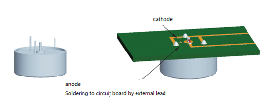
 

 Figure 2Double negative or triple negative lead installation mode (fixed by negative lead)
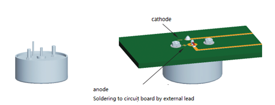


Figure 3Double screw or triple screw installation (fixed by screw)


4.2 Considerations for Installation Method Selection 

Due to the relatively large mass and size of this capacitor, it is advisable to adhere to the following principles during installation:

aFor specifications with large size and mass, standard mounting brackets provided by the manufacturer should be used as much as possible to ensure that the connection between the product and circuit will not experience instantaneous open circuits when the equipment encounters large vibrations and overload impacts, and also to ensure installation strength requirements.

(b) For conditions where size and mass are relatively small and there are stringent requirements for installation space, capacitor products with built-in mounting bolts can be used. For such installations, it is essential to ensure that the circuit board has a high level of strength. Additionally, after tightening the mounting bolts, epoxy-based sealant must be used to secure the bolts. If conditions allow, other forms of fastening (such as applying adhesive to the capacitor base) can also be employed to ensure that the capacitor's mounting strength meets the requirements for extreme conditions of use.

(c) For products used in high-power continuous discharge circuits, capacitors should not be installed too close to devices with significant heat dissipation to prevent the capacitor from overheating and experiencing reduced reliability. Additionally, capacitors used in such circuits should not have heat-insulating sealant coatings applied to their casings to avoid a decrease in heat dissipation performance, which could lead to increased temperatures and reduced reliability of the capacitors.

(d) For products used in high-power uninterrupted discharge circuits, it is essential to have good ventilation conditions to ensure that the heat generated by the capacitors can be promptly expelled, preventing excessive temperature rise of the capacitors.

(e) The anode lead of hermetically sealed high energy tantalum capacitor is connected to the casing with an insulating ceramic material. Therefore, during installation, the positive lead that is fixed to the circuit board must be connected using nickel-based leads that are soldered on; it is not permissible to directly solder the excessively short tantalum leads onto the circuit board. This is because short positive leads can compromise the capacitor's seal when subjected to high overload and high-frequency vibrations, leading to leakage and capacitor failure.


5. Circuit protection


5.1 If the selected capacitor operates at a frequency with significant power variations, it is advisable to implement overload protection in the power supply circuit providing energy compensation to the capacitor. This helps prevent overloading of the power supply when there is a sudden surge in starting current.

5.2 The circuit in which this capacitor is used must have reverse voltage control and a separate discharge path to prevent the capacitor from experiencing reverse surges during operation and shutdown. The energy stored in the capacitor should be correctly discharged after use.


Barcode Scanner is generally divided into three interfaces, namely the USB interface, serial port and keyboard.


1. USB's keyboard mode: It is the same as the USB keyboard. After connecting the scanned gun to the computer, we start to scan the bar code and find that the computer's cursor is located. There is a data input. No matter what software is, as long as the keyboard can be entered, you can scan into the data. The USB keyboard does not need to drive, so the barcode scanning gun that is similar to the USB keyboard does not require driving.


2. USB's serial port mode: In the factory, it is generally used in the factory. For some places with special requirements, you also choose to transmit serial port. This method needs to install the driver. This driver is the driver of the USB transitional chip, and some will be divided into 32 -bit drivers and 64 -bit drivers according to the system. If you want to scan the QR code containing Chinese, you must scan in a serial port. If there is no corresponding software to receive data, you need some small software to pass the data received by the serial port to the cursor.


3. USB HID mode: This method is similar to the USB serial port mode, and it is necessary to install the driver and receive data from the special software from the HID interface.


In retail warehousing management, the barcode solution is adopted. When using barcode scanning guns, pay attention to this: the barcode scanning gun of the serial port cannot be used to use notepads, Excel, Word, etc. The computer comes with it, Win7 is not).


Key step:

1. First connect the data cable to the data cable socket and computer USB port of the barcode scanning gun (the connection method of other interface scanning guns is slightly different, and you can refer to the user manual).

2. Press and hold the trigger key. The lighting light is activated. The red lighting area and the red focus line appear.

3. Met the red focus line on the barcode center, move the scanning gun and adjust the distance between it and barcode to find the excellent knowledge reading distance.

4. Hearing a successful prompt sound, and at the same time, the red lighting line goes off, then the code reads successfully. The scanning gun transmits the decoded data to the host.


Syble is professional barcode scanner manufacturer and supplier, we have a series products of 1D barcode scanner, 2D barcode scanner, desktop barcode scanner and fixed mount barcode scanner. Welcome your inquiry.


In today's healthcare systems, ensuring the utmost safety and efficiency in surgical procedures is of paramount importance. To address this need, the application of Radio Frequency Identification (RFID) technology has emerged as a valuable tool. RFID tags, along with RFID readers, enable the full process traceability of surgical patients from admission to discharge.


RFID technology allows for the automatic identification and tracking of surgical patients throughout their entire hospital journey. Each patient is equipped with a unique RFID tag containing relevant information such as medical history, allergies, and treatment plan. By using RFID readers, healthcare professionals can easily access this information, leading to improved patient care and reduced medical errors.


One application of RFID technology is the use of tag RFID readers located at strategic points within the hospital. These long-range RFID readers can detect and capture patient data in real-time as they move through different areas, such as preoperative, operating rooms, and postoperative recovery. This enables healthcare staff to have instant access to crucial patient information, facilitating seamless coordination and timely decision-making.


Furthermore, handheld RFID readers with displays take the accessibility of patient information to another level. These portable devices provide healthcare providers with the flexibility to scan RFID tags and instantly view relevant patient data on the device's screen. This feature proves particularly useful during emergency situations or when immediate access to patient information is required. Doctors and nurses can make informed decisions at the point of care, enhancing patient safety and overall treatment outcomes.


The implementation of RFID technology in surgical patient tracking offers numerous advantages. It improves patient safety by reducing the likelihood of medical errors due to misidentification or lack of vital information. It enhances workflow efficiency, allowing healthcare professionals to optimize their time and resources. Additionally, it streamlines communication and collaboration among healthcare teams, leading to better coordination and overall patient care.


In conclusion, RFID technology, with the utilization of RFID tags, long-range RFID readers, and handheld RFID readers with displays, brings about significant advancements in surgical patient traceability. This technology empowers healthcare professionals to deliver high-quality care by ensuring accurate patient identification, efficient information exchange, and seamless workflow management throughout the entire surgical process.


As necessary items for patients’ lives, the design of drug packaging should not only meet the  needs of ordinary people, but also consider the special needs of visually impaired people when using  drugs. In view of the problems such as difficulty in identifying and information clarity when using drugs for visually impaired people, relying on the digital technology of intelligent packaging, through the intelligent  packaging cloud platform, the barrier-free design of drug packaging for visually impaired people was  studied from three directions: barrier-free drug information identification, barrier-free drug use process and barrier-free emotional adaptation. The advantages of easy intelligent packaging identification, humancomputer interaction and data analysis were given full play to help guide visually impaired people to use  drugs and achieve the design expectation of barrier-free drug use for visually impaired people.


Packaging digital to packaging as a carrier, through the electronic sensory components, so that packaging to achieve information interaction, data analysis, real-time communication and other functions. Covering barcode and two-dimensional code in pharmaceutical packaging is gradually becoming popular, but visually impaired people will have obstacles and difficulties when using the skills required within the range of vision, such as colour weakness of people with low sensitivity to colours, and it is difficult for blind people to know where the scanning code is, RFID and NFC technology provides visually impaired people with the possibility of information recognition without barriers. RFID is a non-contact automatic identification technology, which uses radiofrequency signals to identify commodities and electronic tags on the packaging to obtain relevant data. RFID is a non-contact automatic identification technology that uses radio frequency signals to identify electronic tags on the packaging of goods in order to obtain relevant data.


By installing RFID on pharmaceutical packaging, visually impaired people can access information about their medicines without scanning in a particular direction and without the need for a scanner. information, the visually impaired person does not need to scan in a particular direction, no need to visualise the mobile device can be used to RFID has low light requirements and can transmit information over long distances. RFID requires less light and can transmit information over long distances, making it easier for the visually impaired to identify drug information. NFC is a form of peer-to-peer communication. NFC is a kind of integrated inductive card chip with peer-to-peer communication function. NFC is a kind of integrated sensor chip with point-to-point communication function, which is implanted in the medicine package to meet the special needs of the visually impaired people. NFC chip technology is implanted in pharmaceutical packaging for the special needs of the visually impaired, and works in conjunction with RFID technology. Through mobile terminals, NFC can realise mobile phone payment, identification, checking and anti-counterfeiting functions. NFC is used in mobile terminals for mobile phone payment, identification, checking and anti-counterfeiting functions.


More and more mobile phones and mobile devices support the provision of NFC functions. More and more mobile phones and mobile devices support the provision of NFC functions, providing sufficient preconditions for NFC to be embedded in pharmaceutical packaging. Visually Impaired The use of smart packaging for medicines with NFC function is simple, no need to scan, very fast, and real-time data is available. It is very fast and easy to scan, and real-time data can be exchanged. The device can point to the pharmaceutical packaging to obtain labelling information such as packaging code, name, ingredients and so on. The smart terminal device can point to the package to obtain labelling information such as package code, name, ingredients, etc., and can also listen to the information with the accompanying Bluetooth headset, which can help to It can also use Bluetooth headphones to listen to the information, which helps to protect the privacy of patients.


2.2 Comprehensive Information Sensing Technology

To meet the needs of different groups of people, pharmaceutical packaging needs to have a selection of targeted sensing technologies for packaging. packaging, making full use of multiple combined sensing system. For example, for drugs with very strict restrictions on storage temperature, the drug packaging can use TTI technology. T T I technology can be used in intelligent packaging, which can effectively detect the temperature in the pharmaceutical packaging environment. The intelligent packaging can effectively detect temperature changes in the pharmaceutical packaging environment and make timely warnings, reducing the omission of manual inspection. It can effectively detect temperature changes in the pharmaceutical packaging environment, provide timely warning and reduce the omission of manual inspection. For drugs that cannot be exposed to light and oxygen for a long time, TTI technology can be installed. For drugs that cannot be exposed to light and oxygen for a long time, light-sensing devices and carbon dioxide sensors can be installed to detect the storage status and openness of the drugs in time. The storage status of the drugs and the use of the drugs after opening can be detected in time, and sound warning can be provided to avoid problems. The installation of light-sensitive devices and carbon dioxide sensors can detect the storage status of medicines and their use after opening in a timely manner. This ensures the safety of medicines by providing audible warnings of problems with medicines, avoiding improper use of medicines by visually impaired people with vision problems.


This study was conducted to establish a new type of the archive management system of ancient and famous trees so as to solve the problems of errors and low efficiency in traditional archive management, while with more and more types and quantities of archive materials. RFID was used to realize the management of file storage, inspection, inventory and failure, for this technology could effectively reduce the manual operation, improve the operation efficiency and realize the automatic and intelligent management of files.

Besides, combined with various sensors, this technology could realize the dynamic real-time monitoring of the archives warehouse, and provide a good storage environment for the ancient and famous tree archives. The intelligent archives management system of ancient and famous trees in Ji’nan based on RFID technology was established by using RFID and Internet of Things technology, combined with information materials, such as the ancient and famous tree resource investigation, identification and protection, maintenance and rejuvenation, daily management, migration approval and so on.


Old and valuable trees are priceless treasures left to mankind by nature and predecessors, with important resource value, humanistic value, historical value, cultural relics value, ornamental value, ecological value and greening scientific research value Combining RFID technology and digital archives construction with scientific management of archives entities to realize a scientific, efficient and highly modernized management of archives construction of the new model has become possible. As an emerging identification technology, RFID technology is widely used in material

As an emerging identification technology, RFID technology is widely used in the fields of material tracking, production automation control, warehousing management, railroad vehicles and freight container identification, etc. [5]. With the increasing maturity of RFID technology, RFID application in archive management, has its reference and feasibility.


RFID-based ancient and valuable trees intelligent archive warehouse management system architecture is mainly divided into data collection, data transmission, data storage and business applications at four levels


Data collection layer is mainly the use of RFID technology, combined with desktop card issuer, file intelligent cabinet, printer, temperature and humidity sensors, water leakage sensors, after the external sensors and other equipment, real-time reading of old and valuable trees file tag information, realizing real-time supervision of the file; data transmission layer is the use of the system's internal network data transmission; data storage layer is the use of the project's servers and the government cloud storage of the mutual backup, to ensure that the archives Data storage layer is the server used in the project and the government cloud storage mutual backup, to ensure the security of the archive data; business application layer is through the cloud computing technology and software development technology, to realize the business application requirements of multi-user.


The RFID-based intelligent archive management system for old and valuable trees mainly consists of four modules: intelligent cabinet management, archive management, security management and dynamic environment monitoring.


Intelligent archive management can provide more convenient archive access experience. Through RFID tags, you can quickly find the required files and realize instant access through the intelligent storage system.


Making full use of RFID technology, it effectively reduces manual operation, improves operation efficiency, and realizes automation and intelligent management of archives; combining with various sensors, it realizes real-time monitoring of the dynamic environment of the archive storage room, and provides a good storage environment for the archives of old and valuable trees.

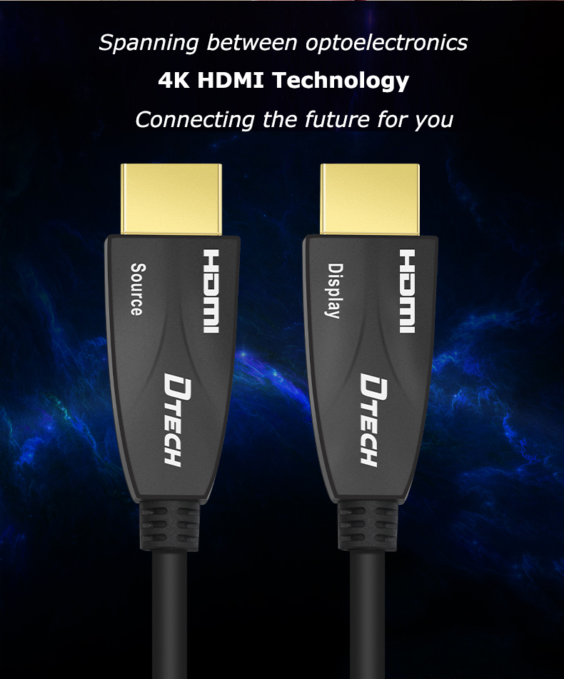
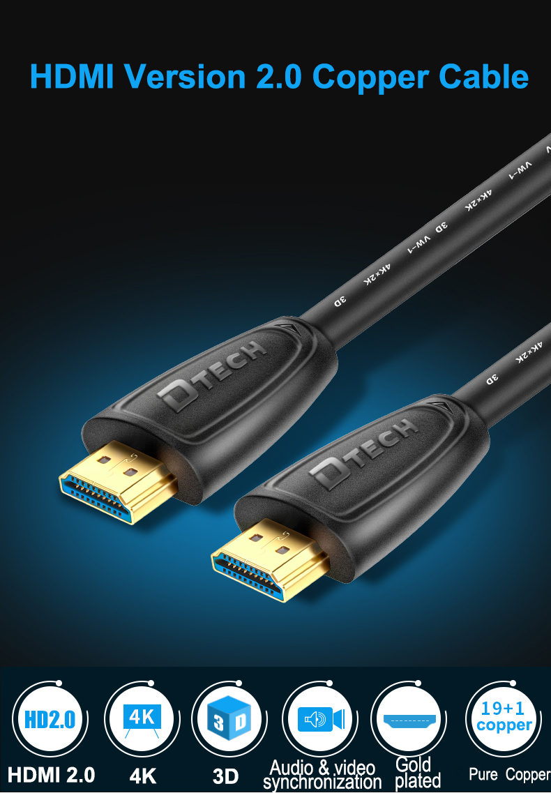
With the development of science and technology, various smart products are being updated. For example, the common HDMI cables in daily life have also undergone 2K, 4K, and 8K changes. The latest standard has been supported to 8K, even 10K, so many versions How to choose when buying wire? Today, Dtech will introduce to you the features of Dtech continuously upgraded HDMI cables! See which one you like more?


1. Dtech HDMI 4K 60Hz HD cable (DT-H001)

This HDMI HD cable supports 3D special effects 4K HD, simultaneous audio and video transmission, helping you build your own home theater, and you can experience the immersive excitement of 3D visual effects at home!

The wire body is made of PVC environmental protection material, the wire core is made of high-quality oxygen-free copper wire core, and the high-density aluminum-magnesium wire braided mesh shield + aluminum foil double-layer shielding truly ensures the safe and stable transmission of signal data. The plug adopts a gold-plated process to effectively reduce resistance and Anti-corrosion effect, more stable signal, non-slip bumps resistant to plugging, durable


2. Dtech Cinematic Fiber HDMI Cable 4K60Hz Engineering Model (DT-HF503)

Dtech HDMI 4K@60Hz high-definition cable, the transmission bandwidth and rate can reach 18Gbps, the frame rate can be increased to 60Hz, and the transmission distance can reach 300 meters, which is much longer than the previous version. Snow, black screen and other phenomena.

The high-definition wire core adopts high-quality optical fiber core, with twisted all copper wire, light-speed transmission, to ensure signal transmission, and decoration and embedding do not have to worry about signal problems! The wire body is made of selected environmentally friendly PVC materials, delicate and soft, easier to wire, one-piece molding, flexible, compact and easy to store!

Guangzhou Dtech Electronics Technology Co., Ltd

HDMI Cable

HDMI Fiber Cable

HDMI 4K 30Hz Fiber Cable


Motor Control refers to the technology and methods for precise control and regulation of electric motors. In the fields of industrial automation and machinery control, motor control is crucial, as it can achieve precise position control, speed control and torque control to drive the movement of mechanical systems.


The basic principle of motor control is to change the operating state of the motor by controlling its current, voltage or frequency. To achieve this, various motor drivers and controllers are typically used to provide the required power and control signals. Key motor control technologies and methods include speed closed-loop control, position closed-loop control, vector control and field-oriented control.


In industrial applications, motor control has a wide range of applications. For example, it can be used in various scenarios such as machine tools, conveyor belt systems, printing presses, robots, textile machinery, chemical equipment, etc. Motor control can increase production efficiency, accuracy and reliability while reducing energy consumption and mechanical wear.


In order to achieve motor control, it is usually necessary to select the appropriate motor type, such as DC motor, AC asynchronous motor (such as induction motor) and AC synchronous motor (such as permanent magnet synchronous motor). Additionally, appropriate drives and controllers need to be selected, and integration with control systems and sensors need to be considered.


Modern motor control systems usually use computer control and digital signal processing technology to achieve high-precision and complex control functions. For example, PID control algorithms can be used to achieve closed-loop speed and position control, combined with pulse width modulation (PWM) technology to control the voltage and current output by the motor driver.


In short, motor control is one of the most important technologies in industrial automation and machinery control. Through precise and reliable motor control, efficient production processes, precise motion control and optimized energy utilization can be achieved. With the continuous development of technology, motor control will play an increasingly important role in various fields, promoting further automation and intelligent development of industry.

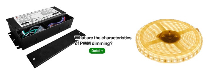
PWM dimming is currently a mainstream dimming technology used in LED dimming power supply products. In the circuit of the analog signal, the brightness change of the lamp is controlled by the digital output. Compared with traditional analog signal dimming, this dimming method has many advantages.


  The basic principle of pwm dimming led driver can be understood as connecting a MOS switch tube in the LED load, and the anode of this string of LEDs is powered by a constant current source. Then a PWM signal is applied to the gate of the MOS tube to quickly switch the string of LEDs to achieve dimming. The advantages of pwm dimming are very obvious, with the following points:


  First,pwm dimming, accurate dimming.

  Precision dimming is a significant feature common to digital signal dimming, because PWM dimming uses pulse waveform signals with high precision.


  Second, pwm dimming, no color cast.

  In the entire dimming range, because the LED current is either at the maximum value or turned off, the average current of the LED is changed by adjusting the pulse duty cycle, so this solution can avoid color shift during the current change.


  Third, pwm dimming, with a large adjustable range.

  PWM dimming frequency is generally 200Hz (low frequency dimming) to more than 20kHz (high frequency dimming).


  Fourth, pwm dimming, no stroboscopic.

  As long as the PWM dimming frequency is higher than 100 Hz, no LED flicker will be observed. Because the LED is in a fast switching state, if the operating frequency is very low, the human eye will feel flicker. In order to make full use of the residual visual phenomenon of the human eye, its operating frequency should be higher than 100 Hz, preferably 200 Hz.


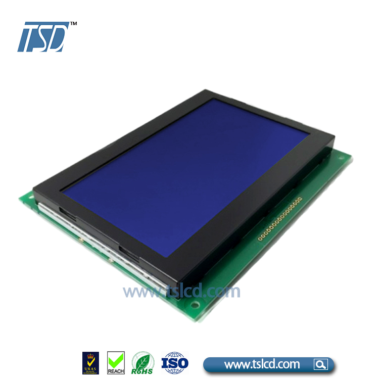
If you need to display only photos can be used in any application screen LCD benefit. Here are a few places where you might find the use of LCD modules:

Hand-held electronics: LCDs can be found in a myriad of hand-held devices such as mobile phones, tablets, portable computers, and so on. They are also seen in digital wrist watches, and in digital compasses. LCDs can render images in full-color and with impeccable clarity. That's the reason they are preferred in such devices.

Consumer devices: There are hundreds of small consumer-oriented devices such as calculators, electronic weighing machines, fixed-line phones, audio and video players, MP3 players, and interactive screens of other devices such as microwave ovens. These devices could have a graphic or character LCD screen. A graphic LCD screen displays all types of images, whereas a character LCD screen only displays alphabets, numerals, and characters.

Automotives: Cars, trucks, trains, airplanes, ships make extensive use of LCD and capacitive touch screens. These are used to either read, or input data. These displays form an integral part of flight instruments, and other navigational devices.

Medical devices: from the family of medical devices such as blood glucose levels and blood pressure monitoring device, in a more complex medical equipment, LCD is widely used in the medical field. Such devices can be integrated capacitive touch. Further, the apparatus may be provided with basic character 'LCD.If you want to know more, visit:tslcd.


Related Reading: graphic LCD module Durable Graphic LCD High Luminance COB LCD


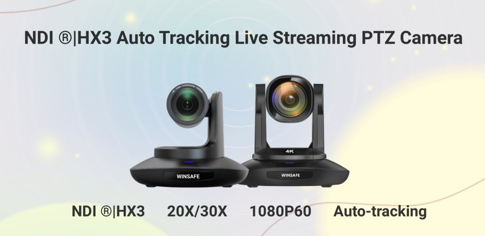
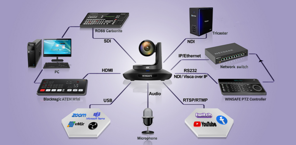
WINSAFE NDI®HX3 Auto Tracking Live Steaming PTZ Camera release, it can be easy used on the training, education and church etc. live steaming situation, Which built-in auto-tracking function, don't need any third-party software or device, just turn on with one click on the WebUI, matching remote control or our control keyboard, and you can track the target accurately and smoothly without any outside interference. You can also switch the target accurately and smoothly without any outside interfrence. You can also switch the target talent, or set the target area, or change the target size. Easy setting, lower latency, better Image.


1080P Full HD 30X/20X, NDI®HX3, NDI®|HX3, 3G-SDI, HDMI and USB2.0 output image simultaneously as well. 3G-SDI and HDMI are for conventional video production workflow, and USB output can be used as a high-end webcam.


Welcome to ask more details and order sample for your testing. UHV-20X-IP-S(ATNDI)